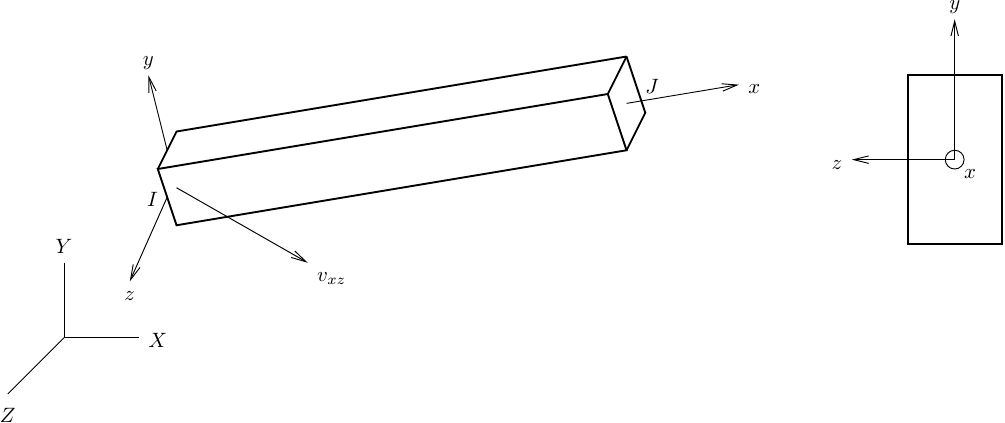
Three-dimensional frame elements require user input for the local element axes. Although the local axis points from node I to node J, there is no automatic way to define the local and axes, i.e., how the section axes line up with the element. In two-dimensions, this is not an issue because the local axis coincides with global , perpendicular to the – plane of the model.
In OpenSees, the user must specify , a vector in the local – plane of 3D frame elements. Then, the geometric transformation class computes the local axis from , followed by the local axis from . Note that the vector can be the actual local axis, but it cannot be equal to .
I’ve never liked this approach to specifying the orientation of 3D frame elements. I have a hard time figuring out a vector in the – plane because I am not very good at geometry. But, even for people who are good at geometry, it is very easy to accidentally rotate the local and axes with this approach.
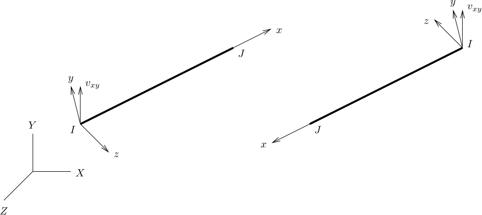
Consider the beam shown below. If we switch the I and J nodes but keep the same , the local and axes rotate by 180 degrees. This lack of invariance can be a problem when defining member loads along the local axis to produce bending about the axis, e.g., for beams in a 3D frame model.
Specifying a vector in the local – plane, let’s call it , would resolve the lack of invariance for the local axis. First compute local from , then compute local from . The local axis is flipped, but that is not too important when you’re applying member loads only along the local axis.
But this post isn’t about member loads in 3D, nor is it about writing new constructors that take as input to the 3D geometric transformation classes. This post is about figuring out the input for OpenSees 3D frame elements without causing a migraine. So, if you want to define your elements such that global vertical is in the local – plane, take an extra step in your input file and let Python calculate the local – vector that OpenSees expects.
# Local x-axis from nodal coordinates
XYZI = ops.nodeCoord(ndI)
XYZJ = ops.nodeCoord(ndJ)
xaxis = np.subtract(XYZJ,XYZI)

# Vectors in the local x-y and x-z planes
vecxy = [0,1,0] # What you want (vecxy is global vertical)
vecxz = np.cross(xaxis,vecxy) # What OpenSees expects

ops.geomTransf('Linear',1,*vecxz)
In addition to elements that lie in a global horizontal plane, this approach will produce the correct local axes for inclined elements that are axisymmetric about the global vertical axis. This is good news for vectorphobes like me. Of course, elements whose local axis aligns with global vertical remain a special case.
I have been involved in the development, maintenance, and growth of OpenSees since its early days. I am interested in learning Python and improving my academic writing.
View all posts by Michael H. Scott
Published
26 thoughts on “A Vector in the x-z Plane”
Hi,
if global vertical is in the local z–x plane, then I should use veczx = [0,0,1]?
Am I right?
Hello Lu,
Yes, if global Z is your global vertical direction. I used global Y as global vertical in the post so that 3D and 2D models would be similar.
PD
This is really insightful and clear!! OpenSees has been a challenge for me and some concepts are difficult to wrap my mind around but “the more that you read, the more things you will know. The more that you learn, the more places you’ll go” and there’s always more I could learn so thank you for sharing your wisdom!
Thank you for a clear explanation.
In that case, for Example 7 in OpenSees manual, shouldn’t the vecxz for girder elements be (-1 0 0) instead of (1 0 0) so that positive local y axis coincide with global vertical Y? The gravity load on girder elements were included with a -ve sign which implies its local y is coinciding with global vertical Y and it is only possible when vecxz is (-1 0 0). Please correct me if I am wrong.
It depends on the I-J orientation of the girder elements. The local x-axis is directed from I to J. You can take all the lateral loads off and analyze for only gravity loads to see if equilibrium is satisfied.
The local x-axis is defined by the end nodes. You can rotate the section *about* the local x-axis by rotating the local z-axis when you define the geometric transformation.
PD


Hi,
if global vertical is in the local z–x plane, then I should use veczx = [0,0,1]?
Am I right?
LikeLike
Hello Lu,
Yes, if global Z is your global vertical direction. I used global Y as global vertical in the post so that 3D and 2D models would be similar.
PD
LikeLike
Thanks for sharing! Definitely a tricky one.
To be 100% sure, Z is out of the page in 2D? As opposed to into the plane.
LikeLike
Correct. In 2D, Z would be out of the page.
LikeLike
This is really insightful and clear!! OpenSees has been a challenge for me and some concepts are difficult to wrap my mind around but “the more that you read, the more things you will know. The more that you learn, the more places you’ll go” and there’s always more I could learn so thank you for sharing your wisdom!
LikeLike
Hello Abby,
Thank you for the comment. So true on the places you’ll go!
PD
LikeLike
Thank you for a clear explanation.
In that case, for Example 7 in OpenSees manual, shouldn’t the vecxz for girder elements be (-1 0 0) instead of (1 0 0) so that positive local y axis coincide with global vertical Y? The gravity load on girder elements were included with a -ve sign which implies its local y is coinciding with global vertical Y and it is only possible when vecxz is (-1 0 0). Please correct me if I am wrong.
LikeLike
Hello Sunil,
Please provide a link to the example.
Thanks,
PD
LikeLike
I tried posting the link here several times but somehow comment isn’t getting posted. Could you let me know an alternate way of sharing link with you?
LikeLike
You can email me the link contact@portwooddigital.com
LikeLike
It depends on the I-J orientation of the girder elements. The local x-axis is directed from I to J. You can take all the lateral loads off and analyze for only gravity loads to see if equilibrium is satisfied.
LikeLike
Hi,
Thank you for enlighten..
But how can I rotate the local x-axis in a beam?
LikeLike
The local x-axis is defined by the end nodes. You can rotate the section *about* the local x-axis by rotating the local z-axis when you define the geometric transformation.
PD
LikeLike