
OpenSees can solve every reasonable problem from any structural analysis textbook. But I nearly had a meltdown over a simple truss problem because truss elements in OpenSees do not directly support thermal loading.
Consider Example 6.17, shown below, from J.C. Smith’s Structural Analysis. All members of the truss have E=29000 ksi, A=10 inch2, and α=6.5e-6 (coefficient of thermal expansion, strain per degree Fahrenheit). The three members indicated in the figure are subjected to a temperature increase of 100 degrees F.
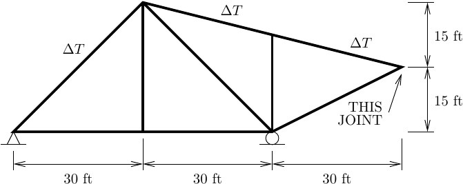
The textbook solution for the displacement of the indicated joint is 0.8970 inch down and 0.4485 inch to the right. In addition, because the truss model is statically determinate, the temperature change should not induce any member forces or external reactions–only displacements.
Because truss elements in OpenSees cannot handle thermal loading (it’s not difficult, just the developers of the thermal modules were focused on frame elements), workarounds are required in order to analyze trusses subjected to temperature changes.
Among workarounds, there is an easy way involving initial strains and a hard way forcing beam elements to behave like truss elements.
The Easy Way
Thermal strain can be treated as an initial strain, so we can wrap an Elastic material with an InitStrain material wrapper where the initial strain is εo=−αΔT. The InitStrain wrapper will send (ε−εo) to its wrapped material, i.e., εo is the stress-free strain, so the negative sign on the change in temperature is correct.
An OpenSeesPy script is shown below for the truss analysis with initial strain wrappers for the heated members.
import openseespy.opensees as ops
from numpy import isclose

kip = 1
inch = 1

ft = 12*inch
ksi = kip/inch**2

ops.wipe()
ops.model('basic','-ndm',2,'-ndf',2)

ops.node(1,0,0); ops.fix(1,1,1)
ops.node(2,30*ft,0)
ops.node(3,30*ft,30*ft)
ops.node(4,60*ft,0); ops.fix(4,0,1)
ops.node(5,60*ft,22.5*ft)
ops.node(6,90*ft,15*ft)

E = 29000*ksi
alpha = 6.5e-6
A = 10*inch**2
dT = 100

ops.uniaxialMaterial('Elastic',1,E)
ops.uniaxialMaterial('InitStrain',2,1,-alpha*dT)

ops.element('truss',1,1,2,A,1)
ops.element('truss',2,2,4,A,1)
ops.element('truss',3,4,6,A,1)
ops.element('truss',4,1,3,A,2)
ops.element('truss',5,3,5,A,2)
ops.element('truss',6,5,6,A,2)
ops.element('truss',7,3,4,A,1)
ops.element('truss',8,2,3,A,1)
ops.element('truss',9,4,5,A,1)

ops.analysis('Static','-noWarnings')
ops.analyze(1)
ops.reactions()

# Verify nodal displacement against textbook solution
ux,uy = ops.nodeDisp(6)
assert isclose( 0.44850,ux/inch,rtol=1e-5)
assert isclose(-0.89700,uy/inch,rtol=1e-5)

# Verify all member forces are zero
for ele in ops.getEleTags():
    assert isclose(0,ops.basicForce(ele)).all()

# Verify all reactions are zero
for nd in ops.getNodeTags():
    assert isclose(0,ops.nodeReaction(nd)).all()
All assertions on joint displacements, member forces, and external reactions should pass. Try it yourself.
The Hard Way
Here’s how to analyze the truss using beam elements with thermal loading capabilities built directly into OpenSees:
- Change the model builder to three DOFs/node to accommodate beam elements
- Fix all rotational DOFs to satisfy the truss modeling assumption
- Define an
ElasticThermaluniaxial material withEandalpha - Define a
FiberThermalsection with one fiber- We do not want flexural response from the section
- One fiber ensures flexural stiffness will be zero
- Define
dispBeamColumnThermalelements- Use
Lineargeometric transformation andLegendrebeam integration - If we used
forceBeamColumnThermal, the element state determination will fail because the section has only one fiber
- Use
- Use a
-beamThermalelement load for the heated elements- The reference locations for temperature gradient through the section depth are irrelevant
- But, the locations have to be non-zero with negative (bottom of section) and positive (top of section) values
An OpenSees Python script using the thermal elements and constitutive models for the truss analysis is shown below with annotations for the points listed above.
import openseespy.opensees as ops
from numpy import isclose

kip = 1
inch = 1

ft = 12*inch
ksi = kip/inch**2

# 1.
ops.wipe()
ops.model('basic','-ndm',2,'-ndf',3)

ops.node(1,0,0); ops.fix(1,1,1,0)
ops.node(2,30*ft,0)
ops.node(3,30*ft,30*ft)
ops.node(4,60*ft,0); ops.fix(4,0,1,0)
ops.node(5,60*ft,22.5*ft)
ops.node(6,90*ft,15*ft)

# 2.
for nd in ops.getNodeTags():
    ops.fix(nd,0,0,1)

E = 29000*ksi
alpha = 6.5e-6
A = 10*inch**2
dT = 100

# 3.
ops.uniaxialMaterial('ElasticThermal',1,E,alpha)

# 4.
ops.section('FiberThermal',1)
ops.fiber(0,0,A,1)

ops.beamIntegration('Legendre',1,1,2)
ops.geomTransf('Linear',1)

# 5.
ops.element('dispBeamColumnThermal',1,1,2,1,1)
ops.element('dispBeamColumnThermal',2,2,4,1,1)
ops.element('dispBeamColumnThermal',3,4,6,1,1)
ops.element('dispBeamColumnThermal',4,1,3,1,1)
ops.element('dispBeamColumnThermal',5,3,5,1,1)
ops.element('dispBeamColumnThermal',6,5,6,1,1)
ops.element('dispBeamColumnThermal',7,3,4,1,1)
ops.element('dispBeamColumnThermal',8,2,3,1,1)
ops.element('dispBeamColumnThermal',9,4,5,1,1)

# 6.
ops.timeSeries('Constant',1)
ops.pattern('Plain',1,1)
ops.eleLoad('-ele',4,5,6,'-type','-beamThermal',dT,-1,dT,1)

ops.analysis('Static','-noWarnings')
ops.analyze(1)
ops.reactions()

# Verify nodal displacement against textbook solution
ux,uy,_ = ops.nodeDisp(6)
assert isclose( 0.44850,ux/inch,rtol=1e-5)
assert isclose(-0.89700,uy/inch,rtol=1e-5)

# Verify all member forces are zero
for ele in ops.getEleTags():
    assert isclose(0,ops.basicForce(ele)).all()

# Verify all reactions are zero
for nd in ops.getNodeTags():
    assert isclose(0,ops.nodeReaction(nd)).all()
Again, all assertions should pass.
Although the model with beam elements and thermal loading is not many more lines than the truss model with initial strains, the cognitive load is much higher.

Dear Professor,
When I use OpenSeesPy-PFEM to analyze the response of a deep-water bridge pier under earthquake action, the difference in displacement at the pier top between the dry (no water) and wet (with water) conditions is much larger than the theoretical difference. When I set the water density to 1 under the wet condition, the pier-top displacements become identical, which indicates that my modeling is generally correct.
However, I cannot figure out what causes the excessively large difference between the dry and wet cases. I have tested both 3D and 2D models, and the discrepancy is even greater in 3D. I suspect that water particles may have penetrated inside the bridge pier. In the 2D model, I used a “line” element for the pier—could the water particles have passed through the 2D pier?
Could you please help me clarify this issue? Thank you very much for your guidance and best regards.
LikeLike
What does this question have to do with the post on thermal loading of trusses.
This is not the OpenSees message board!
LikeLike
Sorry about that, Professor. I just wanted to ask for your advice this way, and it won’t happen again.
LikeLike