Where fiber sections integrate stresses over two dimensions for beam-column line elements, fiber sections integrate stresses through only one dimension for shell elements. Either way, you’re performing volume integrals, whether it’s two dimensions in the section and one in the element or one dimension in the section and two in the element.
The LayeredShellFiberSection, where layers of NDMaterial objects are stacked to make a shell section, is the closest we can get to a generic fiber section for shells. Any NDMaterial, ranging from ElasticIsotropic to AwesomeConcrete, can be used as a layer in a layered shell fiber section.
But one NDMaterial in particular, the PlateRebarMaterial, has caught my attention.
A good example of code re-use by Yuli Huang and Xinzheng Lu, a PlateRebarMaterial object takes any UniaxialMaterial and makes the one-dimensional response multi-axial based on a user-specified angle of orientation. Think of tension steel in a slab.
But what is that angle of orientation relative to the local axes of the ShellMITC4 element? Let’s find out with a simple example.
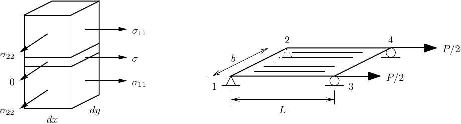
A simple shell section is made up two layers of concrete sandwiching one layer of steel. Not realistic, but I want something that will not make a shell element bend under pure membrane loading.

For the sake of demonstration, all layers are linear-elastic with NDMaterial for the concrete and UniaxialMaterial with PlateRebarMaterial for the steel.
import openseespy.opensees as ops

ops.wipe()
ops.model('basic','-ndm',3,'-ndf',6)

Ec = 3600; nu = 0
Es = 29000

tc = 5.5 # thickness of each outer layer
ts = 1.0 # thickness of the middle layer

ops.nDMaterial('ElasticIsotropic',1,Ec,nu)

ops.uniaxialMaterial('Elastic',1,Es)
theta = 0.0
ops.nDMaterial('PlateRebar',2,1,theta)
                          tag N mat1 thick1 ... matN thickN
ops.section('LayeredShell',1, 3,  1,tc,2,ts,1,tc)
The angle of orientation for the PlateRebarMaterial is input as zero (theta=0.0).
You will also notice I set the Poisson ratio equal to zero in the concrete material so that I wouldn’t have to think too hard about assertions later on.
Anyway, a simple element definition is shown below.
L = 20
b = 12

P = 100

ops.node(1,0,0,0); ops.fix(1,1,1,1,0,0,0)
ops.node(2,0,b,0); ops.fix(2,1,1,1,0,0,0)
ops.node(3,L,0,0); ops.fix(3,0,0,1,0,0,0)
ops.node(4,L,b,0); ops.fix(4,0,0,1,0,0,0)

#                           I J K L secTag
ops.element('ShellMITC4',1, 1,3,4,2, 1)

ops.timeSeries('Constant',1)
ops.pattern('Plain',1,1)
ops.load(3,P/2,0,0,0,0,0)
ops.load(4,P/2,0,0,0,0,0)

ops.analysis('Static','-noWarnings')
ops.analyze(1)
With the node and element definition shown above, the rebars should run along the I–J axis of the ShellMITC4 element (along the global X-axis in this case) with the normal stresses in the shell section shown below (shear stresses in the outer layers not shown for clarity).
And if instead of theta equal to 0.0, we use 90.0 degrees, the rebars should run perpendicular to the I–J axis of the ShellMITC4 element.
ops.nDMaterial('ElasticIsotropic',1,Ec,nu)

ops.uniaxialMaterial('Elastic',1,Es)
theta = 90.0
ops.nDMaterial('PlateRebar',2,1,theta)
                          tag N mat1 thick1 ... matN thickN
ops.section('LayeredShell',1, 3,  1,tc,2,ts,1,tc)
Changing nothing in the element definition, we should now have a model with rebars running along the global Y-axis, as shown below.

How can we make sure the angle of orientation is as expected?
The displacement of nodes 3 and 4 should match the known solution for membrane (axial) loading of this square plate with different material stiffnesses.
For the case of theta=0.0, we can make the following assertion, accounting for some slight round-off.
from math import isclose

Ac = 2*tc*b
As = ts*b

u = ops.nodeDisp(3,1)
uexact = P*L/(Ec*Ac+Es*As)

assert isclose(u,uexact)
And with theta=90.0, the rebar is ineffective and all load resistance comes from the concrete.
u = ops.nodeDisp(3,1)
uexact = P*L/(Ec*Ac) # Steel should be ineffective

assert isclose(u,uexact)
Try this example yourself. You may see different interpretations of theta depending on which shell element you use. Also, see if you can figure out what happens when using the PlateRebarMaterial with the three noded shell elements.

Hello Prof. Scott,
Thank you very much for this post. I am basically using the same as your example. However, I change the location of boundary conditions (fix at nodes 1 and 3), making it like a wall subjected to the lateral load. I am wondering why when I apply the positive load in X direction, the displacement is negative. Could you please explain about this? The displacement in your example was positive. Thank you very much.
import openseespy.opensees as ops
ops.wipe()
ops.model(‘basic’,’-ndm’,3,’-ndf’,6)
import opsvis as opsv
Ec = 3600; nu = 0
Es = 29000
Ec2 = 3900; nu = 0
tc = 5.5 # thickness of each outer layer
ts = 1.0 # thickness of the middle layer
ops.nDMaterial(‘ElasticIsotropic’,1,Ec,nu)
ops.nDMaterial(‘ElasticIsotropic’,3,Ec2,nu)
ops.section(‘LayeredShell’,1, 3, 1,tc,3,ts, 1,tc)
L = 20
b = 20
P = 100
ops.node(1,0,0,0);
ops.node(2,0,b,0);
ops.node(3,L,0,0);
ops.node(4,L,b,0);
ops.fix(1,1,1,1,0,0,0)
ops.fix(2,0,0,1,0,0,0)
ops.fix(4,0,0,1,0,0,0)
ops.fix(3,1,1,1,0,0,0) I J K L secTag
ops.element(‘ShellMITC4’,1, 1,3,4,2, 1)
ops.timeSeries(‘Constant’,1)
ops.pattern(‘Plain’,1,1)
ops.load(4,P/2,0,0,0,0,0)
ops.load(2,P/2,0,0,0,0,0)
ops.analysis(‘Static’,’-noWarnings’)
ops.analyze(1)
u = ops.nodeDisp(4,2)
LikeLike
Hello Prof. Scott,
Please disregard my comment. I was mistaken about the direction when extracting the output node. Thank you.
LikeLiked by 1 person