
Two previous posts showed how to use Minjie‘s meshing functions to create line meshes for beam-column elements and 2D meshes for solid elements. This post will complete the trilogy by showing how to make a 3D mesh for solid elements.
The bar shown below is the same model used in the post on 2D meshing.

To begin a 3D solid model of the bar, define nodes for the eight corner points.
import openseespy.opensees as ops

ops.wipe()
ops.model('basic','-ndm',3,'-ndf',3)

L = 10
h = 2
t = 1

ops.node(1,0, t/2, h/2)
ops.node(2,0,-t/2, h/2)
ops.node(3,0,-t/2,-h/2)
ops.node(4,0, t/2,-h/2)

ops.node(5,L, t/2, h/2)
ops.node(6,L,-t/2, h/2)
ops.node(7,L,-t/2,-h/2)
ops.node(8,L, t/2,-h/2)

The next step is to define line meshes for the edges of the bar. Each of the 12 edges has a tag, followed by information about the end points of each line, the type (use 0 when not FSI), the number of DOFs per node, and the spacing of the nodes along each line.
c = t/2

#              tag Npts nodes type dof size
ops.mesh('line',1,  2, *[1,4],  0,  3,   c)
ops.mesh('line',2,  2, *[4,3],  0,  3,   c)
ops.mesh('line',3,  2, *[3,2],  0,  3,   c)
ops.mesh('line',4,  2, *[2,1],  0,  3,   c)

ops.mesh('line',5,  2, *[5,8],  0,  3,   c)
ops.mesh('line',6,  2, *[8,7],  0,  3,   c)
ops.mesh('line',7,  2, *[7,6],  0,  3,   c)
ops.mesh('line',8,  2, *[6,5],  0,  3,   c)

ops.mesh('line', 9, 2, *[1,5],  0,  3,   c)
ops.mesh('line',10, 2, *[2,6],  0,  3,   c)
ops.mesh('line',11, 2, *[3,7],  0,  3,   c)
ops.mesh('line',12, 2, *[4,8],  0,  3,   c)
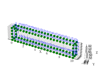
Compared to 2D meshing, 3D meshing requires an extra step before creating elements–nodes must be generated over each of the six faces of the bar. Call the mesh command with mesh tag, the number of lines that circumscribe the face, the line tags, the type (still 0), DOFs per node, and mesh size–but leave off the element arguments.
meshType = 'tri'
#meshType = 'quad'
#                tag  Nlines   lines   type dof size
ops.mesh(meshType,13,   4,  *[1,2,3,4],  0,  3,   c)
ops.mesh(meshType,14,   4,  *[5,6,7,8],  0,  3,   c)
ops.mesh(meshType,15,   4,  *[4,9,8,10], 0,  3,   c)
ops.mesh(meshType,16,   4,  *[2,12,6,11],0,  3,   c)
ops.mesh(meshType,17,   4,  *[3,11,7,10],0,  3,   c)
ops.mesh(meshType,18,   4,  *[1,12,5,9], 0,  3,   c)
For a quadrilateral mesh on each face, simply change 'tri' to 'quad'. The nodes created on all six faces are shown below. Yeah, it’s a little crowded, but when you give this a try, you can zoom and rotate the view to see what’s going on.


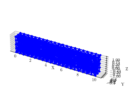
With nodes on all six faces of the bar, we can now create the element mesh. The only element available for 3D meshing with the mesh commands is the four node tetrahedral element. For brick elements, your only option for now is to use the block3D command.
E = 29000
v = 0.3

ops.nDMaterial('ElasticIsotropic',1,E,v)

#             tag Nlines     lines         type dof size <ele args>
ops.mesh('tet',20,  6,*[13,14,15,16,17,18],  0,  3,   c, 'FourNodeTetrahedron',1)
Again, the views are pretty crowded, but you can zoom and rotate when you give this a try.

To apply boundary conditions along a surface, you can use fixX, fixY, and fixZ. To fix the displacements of all nodes with X-coordinate equal to 0, use the following command.
#        X 1 2 3
ops.fixX(0,1,1,1)
As far as I know, there’s no easy way to apply traction stresses to solid models in OpenSees. While this functionality can be implemented via scripts, it should be implemented within the OpenSees core.
The meshes shown in this post were plotted using the opsvis package developed by Seweryn Kokot.

Hello Mr.Scott,
I am basicly trying to investigate mode shapes and eigen values of structures with large slabs using with shell elements such as “ShellMITC4” or “ShellDKGQ” in OpenSees. I am using the precudure that you provided here for shell elements.
However, While 2D example works well, in 3D example, my kernel is constantly restarting.
I know something is wrong in this line below, but couldn’t figure it out.
ops.mesh(‘tet’,20, 6,*[13,14,15,16,17,18], 1, 3, c, ‘FourNodeTetrahedron’,1)
LikeLiked by 1 person
Hello Zafer,
There is an issue in the Windows version of the 3D tetgen function which is causing the kernel to die. I did the examples on Linux.
Michael
LikeLiked by 2 people
Thanks a lot. I will try on Linux.
LikeLike
Hello Mr.Scott,
I have two questions to ask you and hope to get your answers. First, when I reproduced the content from your blog, the result I got was: the process has ended with exit code -1073741819 (0xC0000005). Some say it’s a version issue, but I’m currently using the latest version 3.7.1.2. How should I resolve this?
Secondly, I am currently trying to extend PFEM from 2D to 3D. I am using 3D beam elements, but they have 6 degrees of freedom while PFEM has 3, and it keeps giving errors. So, in 3D PFEM, can I only use the mesh solid elements that you mentioned in your blog?
LikeLike
The three dimensional mesh may have some issues on Windows. Try on Linux.
LikeLike
Thank you, Professor
LikeLike
Professor, I appreciate your effort in answering another question. I have extended PFEM from 2D to 3D. In OpenSees, 3D has 6 degrees of freedom, while PFEM has 3 degrees of freedom, which frequently causes errors. In this case, how should we set it to resolve the issue—should we calculate using 6 degrees of freedom or 3 degrees of freedom? Thank you very much, Professor, and I look forward to your reply.
LikeLike