
A “leaning column” approximates the global P-Delta effects of gravity loads supported by vertical load resisting systems that are connected to, but not explicitly included in models of, lateral load resisting systems. The leaning column approach can simplify the analysis of frame structures for lateral loads, as well as gravity loads with initial out-of-plumb imperfections.
Heavy Industrial Frame
The 11-bay frame shown below, from a heavy industrial building, is ideal for demonstrating the leaning column approach. The central bent (moment frame) provides lateral load resistance while the ten outer columns (five on either side of the central bent) resist gravity loads only. Nominal dead and live loads of 2.8 kip/ft and 1.4 kip/ft, respectively, are applied across the girder.

This frame has been studied by several researchers to determine the frame’s stability under gravity loading, as well as combined gravity and wind loading in Surovek-Maleck and White (2004).
The outer columns will contribute to global lateral instability by P-Delta effects. However, modeling all ten outer columns can become tedious and is ultimately unnecessary.
Assuming rigid diaphragm behavior, accounting for P-Delta effects on one gravity column is equivalent to accounting for P-Delta effects on multiple gravity columns. The logic is that if the gravity columns have the same Delta, then we can put all the P on one column.
Accordingly, we can reduce the model of this frame from 11 bays down to three: one moment-resisting bent and two leaning columns.
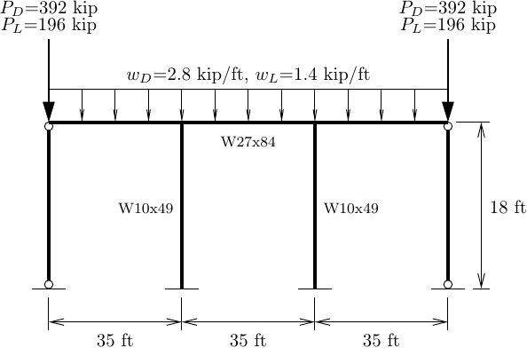
The concentrated dead and live loads on each leaning column are 392 kip and 196 kip, respectively, based on the distributed loads applied over four bays, i.e., 2.8 kip/ft and 1.4 kip/ft over 140 ft.
Applying concentrated loads to two leaning columns in this model is a choice that preserves symmetry, but we can put all eight bays worth of gravity load on one leaning column and see only minor differences in the global response.
Leaning Columns in OpenSees
Truss elements are often used for leaning columns, but in OpenSees, the truss element does not have an option for P-Delta effects. You could use the corotational truss element, but that brings on more geometric nonlinearity than is necessary for global P-Delta.
The best approach to model a leaning column in OpenSees is to use an elastic beam-column element with moment releases and the P-Delta geometric transformation. The cross-sectional area of the element need not be artificially high to mimic axial rigidity and invite ill-conditioning, but instead should be realistic.
An analysis script for the heavy industrial building frame with leaning columns is shown below. The frame has initial out-of-plumbness equal to 1/500 times the column height and the PDelta geometric transformation is used for the leaning columns and the columns of the central bent. The total gravity load (dead plus live) is defined in a linear time series and increasing the load factor under load control will lead to lateral instability.
import openseespy.opensees as ops

kip = 1
inch = 1

ft = 12*inch
ksi = kip/inch**2

E = 29000*ksi

wD = 2.8*kip/ft
wL = 1.4*kip/ft
PD = 392*kip
PL = 196*kip

ops.wipe()
ops.model('basic','-ndm',2,'-ndf',3)

ops.node(1,     0,0); ops.fix(1,1,1,0)
ops.node(2, 35*ft,0); ops.fix(2,1,1,1)
ops.node(3, 70*ft,0); ops.fix(3,1,1,1)
ops.node(4,105*ft,0); ops.fix(4,1,1,0)

h = 18*ft # Column height
oop = h/500 # Out-of-plumbness

ops.node(11,     0+oop,h)
ops.node(12, 35*ft+oop,h)
ops.node(13, 70*ft+oop,h)
ops.node(14,105*ft+oop,h)

# Leaning columns
A = 100*inch**2 # Large, but not very large
I = 1000*inch**4 # Doesn't matter, needs to be > 0
ops.geomTransf('PDelta',1)
ops.element('elasticBeamColumn',1,1,11,A,E,I,1,'-release',2) # Release end J
ops.element('elasticBeamColumn',4,4,14,A,E,I,1,'-release',2)

# Columns of central bent
# W10x49
A = 14.4*inch**2
I = 272*inch**4
ops.geomTransf('PDelta',2)
ops.element('elasticBeamColumn',2,2,12,A,E,I,2)
ops.element('elasticBeamColumn',3,3,13,A,E,I,2)

# Girder
# W27x84
A = 24.7*inch**2
I = 2850*inch**4
ops.geomTransf('Linear',3)
ops.element('elasticBeamColumn',11,11,12,A,E,I,3)
ops.element('elasticBeamColumn',12,12,13,A,E,I,3)
ops.element('elasticBeamColumn',13,13,14,A,E,I,3)

ops.timeSeries('Linear',1)
ops.pattern('Plain',1,1)
ops.load(11,0,-(PD+PL),0)
ops.load(14,0,-(PD+PL),0)
ops.eleLoad('-ele',11,12,13,'-type','beamUniform',-(wD+wL))

lamMax = 1.8
Nsteps = 20
dlam = lamMax/Nsteps

ops.integrator('LoadControl',dlam)
ops.analysis('Static','-noWarnings')

for i in range(Nsteps):
    ops.analyze(1)
In this model, the columns of the moment-resisting central bent are linear-elastic, but these elements can easily be swapped out for material nonlinear elements with fiber sections and/or a corotational mesh of elements to simulate P-little-delta effects, as done by Buonopane (2008) using OpenSees. Note that the leaning columns are unaffected by modeling decisions for the lateral load resisting system.
The computed relationship between load factor and lateral deflection is shown below.
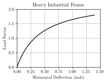
Due to the large gravity loads, the frame loses lateral stiffness at very low lateral deflection, less than 1% of the column height. Analysis of the full 11-bay frame, explicitly modeling P-Delta effects in each gravity column, showed little difference in the lateral response.
Although the example shown in this post was a single story frame, this approach to approximating global P-Delta effects can be applied to multi-story buildings by defining leaning columns for every story.

Thank you very much for your post, Professor Scott. It’s really helpful for OpenSees users.
I have a quick question about nodal mass assignment: in your script, it looks like no mass is specified. If the model is intended for dynamic analysis, would you typically assign mass to the girder nodes only, or to both the girder nodes and the leaning column nodes?
Thank you for your time and consideration.
LikeLiked by 1 person
Good question! For the horizontal DOFs with rigid diaphragm, it shouldn’t matter where you assign the mass. But if you assign mass to vertical DOFs, the distribution matters.
LikeLike
Thank you, Professor Scott. In my 2D models I typically don’t include mass of the vertical DOF, so my confusion is mainly about how to handle mass in the horizontal DOFs when a leaning column is used.
Could I please confirm my understanding?
The corresponding additional mass from the gravity system can be lumped to either the leaning column nodes or the frame nodes, as long as the total seismic mass is represented correctly.
In other words, it would still be acceptable for the leaning column to carry the vertical load while having no assigned mass.
Please let me know if I’ve misunderstood anything. Thank you very much!
LikeLike