This post follows three-act structure in verifying the flexural and shear response of the TwoNodeLinkSection element.
Setup
I’ve been working on the TwoNodeLinkSection element, which is like a TwoNodeLink, but uses a section object instead of multiple uniaxial materials. Basically the same spin the ZeroLengthSection puts on the ZeroLength element.
Using a section object inside a two node link element will simplify modeling strategies for walls and base isolators, where interaction of section forces is important. Because there’s a length involved, the TwoNodeLinkSection element should also clear up the fuzzy zero length logic that has penetrated OpenSees users’ bond slip models.
Confrontation
In my early trials with the TwoNodeLinkSection, I had some doubts about how the element length plays with the section response. So I used a simple verification example to make sure I understood what’s going on before moving on to walls, base isolators, and bond slip.
In a two node link element, the user specifies the section location as a fraction, c, of the element length, measured from node I to node J. Also, for simple two node link models, the section must provide shear resistance; otherwise, the analysis will fail to solve.
We can use the principle of virtual forces (PVF) to compute deflections and understand what a two node link element does with a section. The element assumes constant deformation (axial, curvature, shear, etc.) along its length, kinda like a beam-column element with one integration point.
For a lateral load P applied at the free end, the bending moment is P(1-c)L and the shear is P at the section location. Then, the section curvature and shear deformation are P(1-c)L/(EI) and P/(GAv), respectively. These section deformations are assumed constant over the entire element length, giving the “real” curvature and shear deformation shown below. The virtual loading leads to virtual moment and shear equal to (1-c)L and 1, respectively, at the section location.
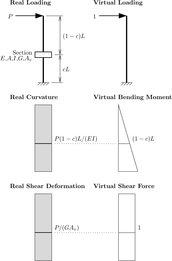
The weird thing about applying the PVF to the two node link element is you have to refrain from integrating “rectangle-triangle” and “rectangle-rectangle” like shown in the table on the front or back flyleaf of your favorite structural analysis textbook. Instead, take a step back and evaluate the virtual moment and shear not at the centroid location (0.5L) of the real section deformation diagrams, but at the user-specified section location, cL, which may not be at the centroid.
Multiplying the areas of the real section deformation diagrams, P(1-c)L2/(EI) for curvature and PL/(GAv) for shear deformation, by the corresponding virtual moment and shear, (1-c)L and 1, respectively, then summing the internal work done by flexure and shear gives the following expression for the free end deflection:

The script for this analysis of a two node link with an elastic section is shown below.
import openseespy.opensees as ops
from math import isclose

P = 10
L = 48

E = 29000
v = 0.3
G = 0.5*E/(1+v)

A = 20
I = 800
alpha = 0.8
Av = alpha*A

ops.wipe()
ops.model('basic','-ndm',2,'-ndf',3)

ops.node(1,0,0); ops.fix(1,1,1,1)
ops.node(2,0,L)

ops.section('Elastic',1,E,A,I,G,alpha)

c = 0.4 # or whatever
ops.element('twoNodeLinkSection',1,1,2,1,'-shearDist',c)

ops.timeSeries('Constant',1)
ops.pattern('Plain',1,1)
ops.load(2,P,0,0)

ops.analysis('Static','-noWarnings')
ops.analyze(1)

assert isclose(ops.nodeDisp(2,1),P*(1-c)**2*L**3/(E*I)+P*L/(G*Av))
Will the deflection match the closed-form solution obtained via the PVF?
Resolution
Yes, the assertion passes for any value of c. Try it yourself.
My worry that the TwoNodeLinkSection element would require or impose an unexpected length scaling between the section and element response was unfounded and has been put to rest. Onward to more complex cases with fiber sections, i.e., the MVLEM suite of elements, then onto base isolators and bond slip.
