
If you’ve used the force-based beam-column element in OpenSees, you’ve likely come across this warning involving element forces and deformations:
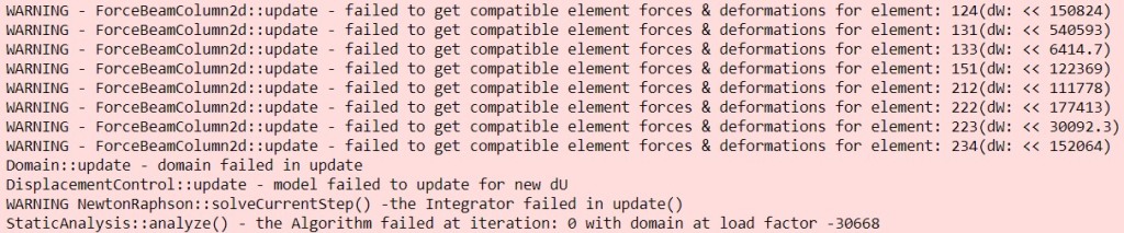
I’ve encountered this warning many times and so have others. In fact, I lifted the above image from a recent post on the OpenSees Facebook group.
I tried to come up with a MWE to demonstrate the issue in this post, but failed. I didn’t try too hard though because I know what causes the “failed to get compatible …” message. The lack of a MWE didn’t stop me from punching the keys.
But before we get into what causes the issue, let’s look at what the output tells us, from the bottom up, in the above image.
The static analysis “failed at iteration 0 with domain at load factor -30668”. The message should say ‘step’ and not ‘iteration’. Web edits on GitHub are great for simple fixes–wording changed. So, the analysis failed at the first (pseudo) time step of the analyze command. If you have analyze(1) inside a loop in your script, you’ll see 0 regardless of the time in the domain. Use getTime() to find out the time step where the analysis failed.
At any rate, the load factor of -30668 indicates the displacement control integrator and Newton algorithm are flailing around looking for a solution, as shown in the preceding two lines of output. Such a large negative load factor is not a good omen in a pushover analysis.
Moving on, the DisplacementControl::update() method fails because Domain::update() failed, which failed because ForceBeamColumn::update() failed. Each “failed to get compatible …” warning message tells us the tag of the offending element. In this case elements 234, 223, 222, etc.
The final piece of output, dW, requires a little background on the force-based element implementation in OpenSees.
In its original form, the force-based element requires nested Newton loops in order to ensure equilibrium between basic forces and section forces as well as compatibility between section deformations and element deformations. Iterate on element compatibility and within that loop, iterate on section equilibrium at each integration point. The nested loops can be computationally intense, so Neuenhofer and Filippou developed a non-iterative formulation that propagates the internal element residuals up to the global Newton iteration. One trip in, one trip out, just like standard displacement-based elements.
But the trips in and out are still moderately intense, so we don’t want to do make two trips–one for getResistingForce() and another for getTangentStiff()–for every force-based element at every global Newton iteration. Instead of implementing the non-iterative state determination twice in OpenSees, Frank jammed the state determination for resisting force and stiffness into the ForceBeamColumn::update() method, which is called once at each global Newton iteration. This is why you see the “failed to get compatible …” error emanating from the ForceBeamColumn::update() method.
However, if you look at the implementation, you’ll see that the non-iterative approach is not what happens in the ForceBeamColumn::update() method. Instead, the element implements its own “smart analyze” algorithm.
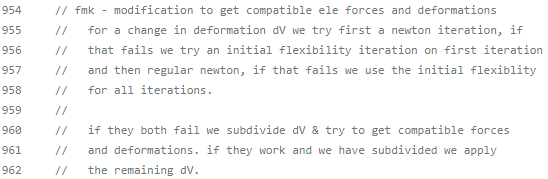
The element will first try to satisfy compatibility using an internal Newton iteration, i.e., with the tangent element flexibility. If that fails, the element tries “initial then current” Newton iteration and the final attempt is iteration with the initial element flexibility.
If none of the local Newton variations converge, the target element deformations are subdivided and then the element runs through the Newton variations again. This subdivision is akin to reducing your global time step.
If element compatibility and section equilibrium are not satisfied after subdivisions and local Newton variations, we get to the “failed to get compatible …” warning. Instead of returning 0 for a successful call to update(), a -1 is returned setting off the previously described chain of messages in the OpenSees output.

The variable dW is the incremental work, i.e., the dot product of the increment in element deformations with the increment in basic forces from the non-converged state at the final element state determination attempt, i.e., after exhausting subdivisions and Newton variants. The magnitude of this number is not so useful, but if it’s negative, the element may have issues with localization or the element is in some bizarre, non-unique trial state.
Then what causes non-convergence within the force-based element, giving us the “failed to get compatible …” warning message? It’s the section constitutive response.
The response of one or more sections is bad, e.g., due to excessive deformations, near singular section stiffness, fiber sections with crappy uniaxial materials like Concrete23, or incorrect layout of section fibers, i.e., your fibers are oriented the wrong way for 2D bending or you didn’t discretize in both directions for 3D bending.
It’s always the section constitutive response.
So, check your model. The output tells you which element is causing problems. From there, look at the force-deformation response of each section. Your model could also have a problem with multi-point constraints causing unrealistic trial states in the elements.
However, it’s not always a model issue. This warning can legitimately appear when your model is loaded beyond its plastic capacity or has collapsed. Just be sure to rule out odd section response.
With internal Newton iterations and a “smart analyze” feature, each force-based element is like a little structural model. A structural model for ants …

Great explanation Prof. Scott! It’s always interesting to know what is reason and the meaning of warning or error messages. Thank you very much.
LikeLiked by 1 person
I have a question about this statement in the post: “Your model could also have a problem with multi-point constraints causing unrealistic trial states in the elements.” How do we resolve this?
LikeLike
That is impossible to answer without knowing more details. Use different constraint handlers. Try different elements and/or materials. Use smaller time steps. Track it down.
LikeLike
Thank you for your reply. I am analysing a steel MRF (10 storey 5 bay) for transient dynamic analysis. I am Transformation for constraints and UmfPack for SOE. I am using a combination of zero length spring elements and rigid elements to model joints in my model. MP constraints are used in the joint region. Trying to figure out the error in a systematic manner, I reached a conclusion that initial stiffness of the zero length elements causes a convergence and negative eigenvalue issue in the problem. Just by simply changing the mesh size of the beam does help with the issue. Is changing the mesh size of the beams , a valid solution for the errors encountered? Does it reflect that the error is due to some numerical issues in the problem while integrating?
When I am using the same joint model for a much smaller problem like a sub-assembly or a smaller frame (3bay 3storey), no such problems arise even during probabilistic analysis for a large sample size (~20,000). Is is possible that the size of the frame is playing a role in causing the error?
LikeLike
Probably not. Sounds like a modeling error, which is pretty common with the rigid element and spring models.
LikeLike
Thanks for the reply. I’ll try to figure out the issue.
LikeLike
Thanks Prof, Scott. I’m wondering if there’s a way to turn off the printing of this warning off when running models.
LikeLike
Use the logFile command
LikeLike
Thank you! One more question: Is there one way to avoid them at all?. We’re trying to run several nonlinear analyses and we want to avoid terminal output and any operation that uses the SSD drive?
LikeLike
Thank you for the explanation.
I wanted to know if there is dependency of uniaxial material being stable on type of element formulation used for analysis. For example I am analyzing a simple pinned supported slender brace with compact section using SLModel for material constitutive relationship. With force based formulation opensees shows the above error (failed to get compatible forces and deformation) but with displacement formulation, the material model simulates the response sufficiently accurate. ( Checked for 30 and 8 number of elements with 5, 7, and 10 integration points and 0.001 very small incremental displacement. In all the cases displacement formulation worked while force formulation gave error)
LikeLike
Hard to tell from the details you provide, but likely the SLModel has zero tangent or some instability somewhere in its response. I’m not familiar with the SLModel does.
LikeLike
Thank you for your response.
I apologize that I did not include background information on the material model. In brief, SLModel was developed to capture the cyclic deterioration in columns due to local buckling. It builds on top of the UVC material model to capture hardening behavior. The original author used force-beam column element with plastic hinge for the analysis and validation.
If there is instability in the SLModel, wouldn’t the displacement formulation also be affected? Additionally, thank you for the helpful hint
LikeLike