
For material nonlinear analysis of frame models, you can improve the computed response by using more displacement-based elements or more integration points in a force-based element. The material nonlinearity occurs inside the basic system, also known as the natural system or the kernel.
To capture geometric nonlinearity due to large displacements, you have to go outside the basic system with the P-
But capturing geometric nonlinearity inside the basic system, i.e., P-
Fortunately, the large displacement transformation outside the basic system is independent of what’s going on inside the basic system. So, instead of using a more complex element formulation, you can use a small strain formulation for each element in a corotational mesh and get P-
Let’s demonstrate the idea with a 15 ft long W10x54 column buckling about its weak axis. The section area is 


To trigger buckling in the subsequent analyses, the nodal locations are defined by a first mode buckled shape with an initial imperfection of 
Elastic Buckling
The elastic buckling load for the column, 


The axial load-displacement response is shown below for 

We will use six elements for the analyses in the following section.
Inelastic Buckling
This column is not slender enough to buckle elastically because the crushing load, 

To capture inelastic buckling, we can use material nonlinear beam-column elements in the corotational mesh. Since we are using a discretized mesh to capture the geometric nonlinearity, we might as well go with the displacement-based formulation for the material nonlinearity.
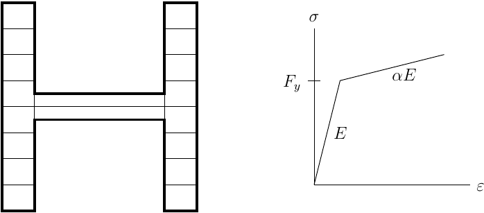
A fiber discretization about the weak axis simulates the force-deformation response at each integration point. The stress-strain response of each fiber is bilinear with the given 
The computed axial load-displacement relationship is shown below, again using displacement control. As expected, we come in under the crushing load; however, we over-predict the nominal strength by about 50 kip.

Why are we over-predicting the nominal compressive strength reported in the Steel Manual? Recall that the Steel Manual uses an empirical relationship to account for residual stresses in the compressive strength tables. So, we should get closer to the nominal strength if we use residual stresses in the analysis.
To this end, we can use the InitStressMaterial in OpenSees to define a residual stress pattern across the fiber section. The linear approximation of the Lehigh pattern is a simple approach (see Fig. 6a here).

Recomputing the axial load-displacement response with 


Note that it’s a good idea to get the initial stresses into equilibrium with one analysis step prior to applying loads with displacement control. It took me a while to remember this after trying to wrap my head around why the displacement-controlled analysis failed well before reaching the nominal compressive strength.

When doing elastic buckling analysis, what is the art of determining the incr of integrator DisplacementControl.
LikeLiked by 1 person
Hello ZHU,
Good question! A quick way to do this would be to compute the Euler buckling load, P, then find a reference axial displacement from U=PL/EA. Then take increments in displacement control on the vertical DOF equal to U/100. It’s kind of a dark art 🙂
PD
LikeLike
In the Last plot how it is possible to apply a lesser load yet getting large displacement. How to apply load beyond the peak point or how to achieve decreasing trend of the plot.
LikeLike
Hello Praveen,
You can go past the peak point using the DisplacementControl integrator instead of LoadControl.
PD
LikeLike
Thank you for your kind reply,
Actually what I am doing is applying a vertical load and noting the displacement for that particular load. However from your plot, it appears that you have increased the load from 0 to the peak value, I am unable to understand how did you reduce the load after the peak load and yet you were able to get large displacement. In my case I am getting plot till the peak after that I am facing a convergence problem. It would be helpful if you tell me how to apply load using displacement control.
LikeLike
Here is an example. You can find other examples online.
https://github.com/OpenSees/OpenSees/blob/master/EXAMPLES/ExamplePython/Example3.2.py
Also, try the message board: https://opensees.berkeley.edu/community
LikeLike
Thank you sir
LikeLike
Dear sir, After your suggestion, I did a gravity analysis. After that, I defined load pattern and displacement control integrator as shown below
pattern Plain 2 Linear {
load 161 0. -1.0 0.0
}
test EnergyIncr 1.0e-8 300 1
algorithm KrylovNewton
system UmfPack
numberer RCM
constraints Plain
analysis Static
set dU 0.0002
integrator DisplacementControl 161 2 $dU 1 $dU $dU
analyze 10
But how to apply the load lesser than the peak load and yet getting large displacement.
LikeLike
Please post your modeling question on the OpenSees message board: https://opensees.berkeley.edu/community
LikeLike
Hello,
thank you for your valuable post.
I searched your site for an explanation about twoNodeLink but found nothing. Can you provide an explanation for this element and how it works.?
LikeLike
It’s similar to a zero length element, but can have non-zero length.
https://opensees.berkeley.edu/wiki/index.php/Two_Node_Link_Element
LikeLike
Great article!!
Can this buckling simulation, using displacement-based beam-column elements with nonlinear material (fibers), be used for histeretic behavior? I mean in a dynamic analysis, for example.
TY.
LikeLike
Thank you! Yes, this approach can be used for cyclic loading with hysteretic material behavior.
LikeLike
Good explanation!
LikeLiked by 1 person